Let the mechanism show
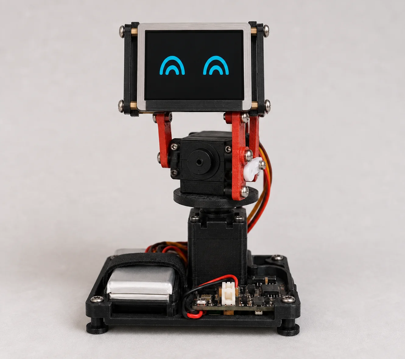
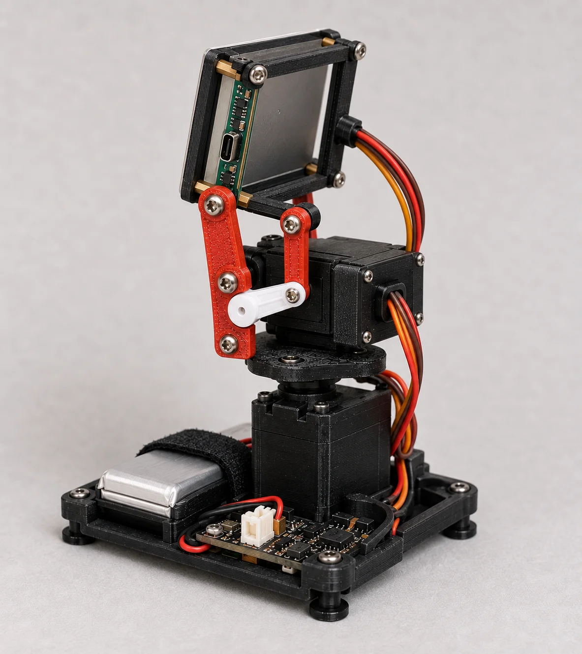
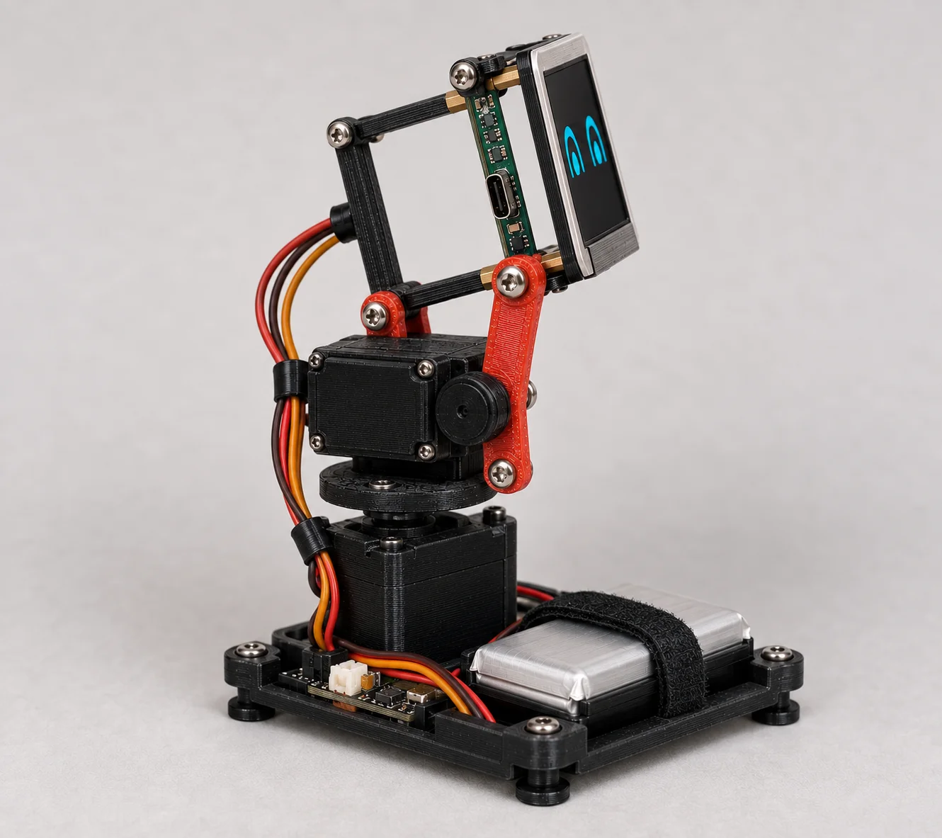
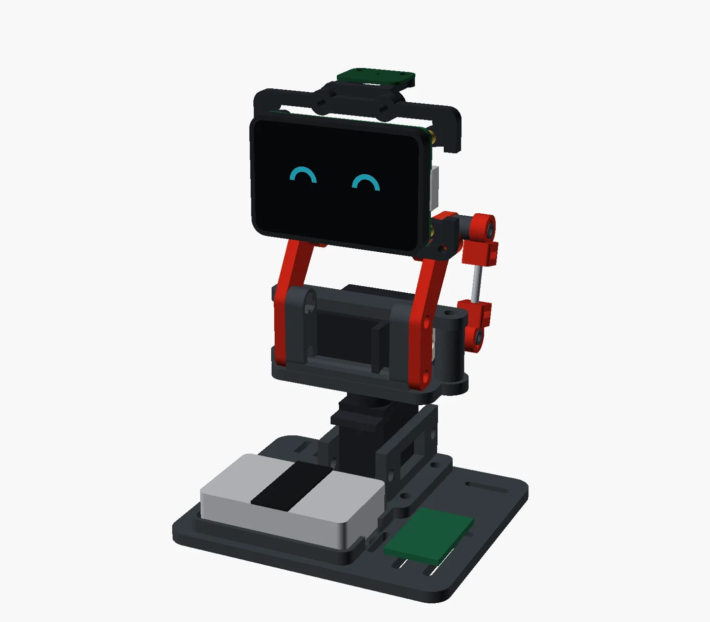
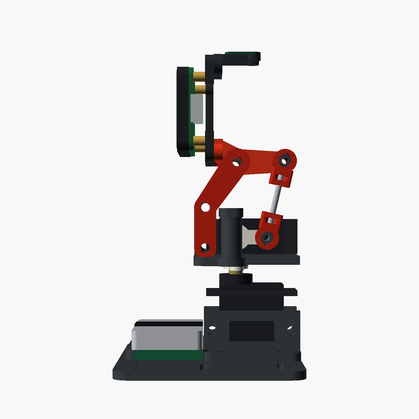
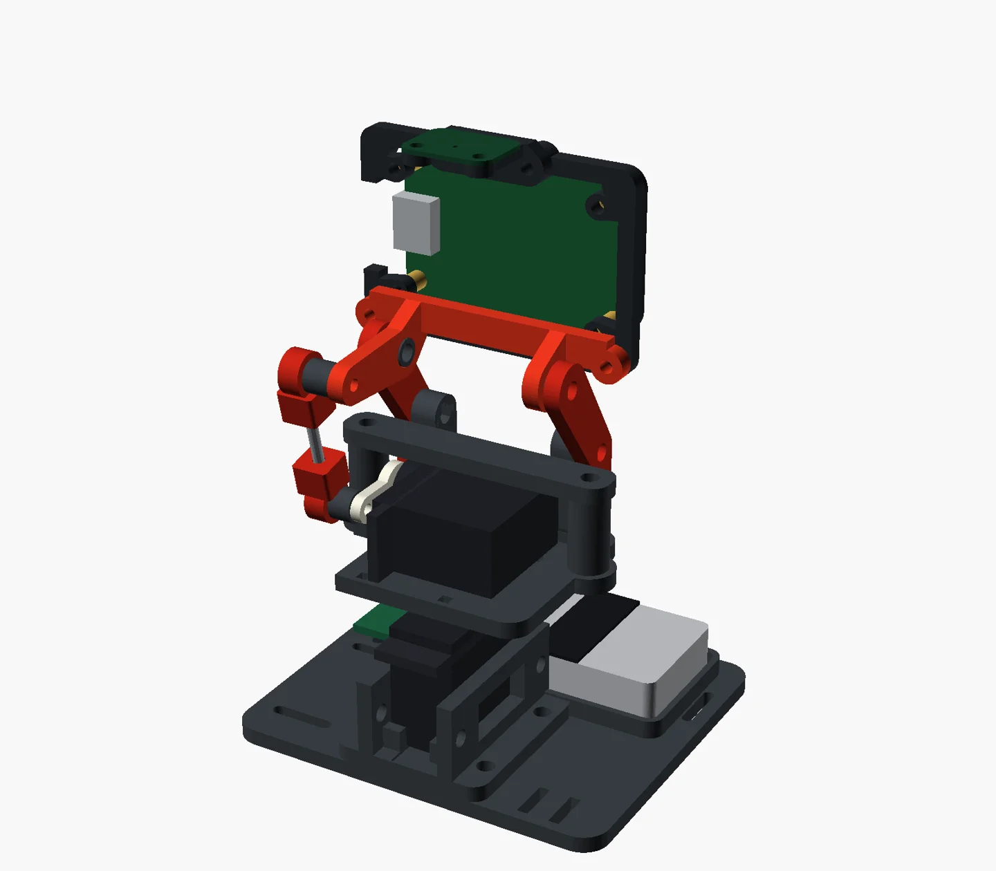
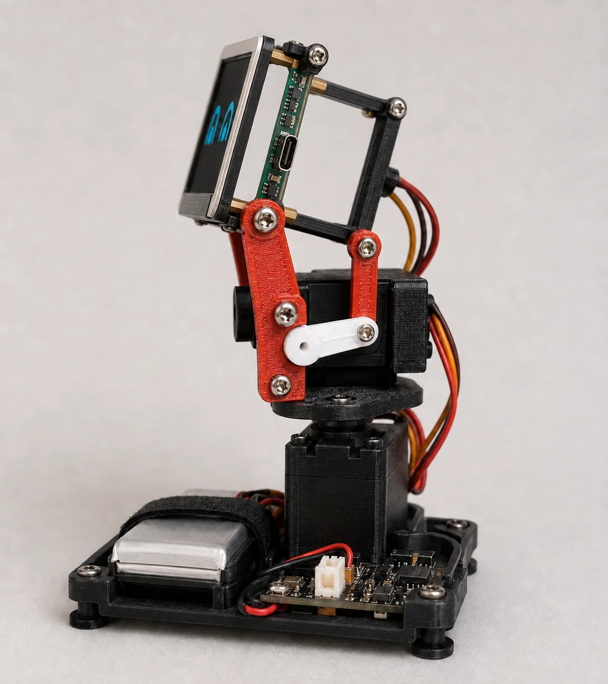
The open-frame idea is simple: stop hiding the good stuff. Servos, brackets, and linkage stay in view. A small screen sits above a pair of red supports, and a metal pushrod carries the tilt motion right beside the head. The first pictures here are appearance studies; the later views come from the actual CAD.
Turn the idea into parts
An idea gets real when it becomes a parts list. The v1 package is 23 individual STL files, counting fit gauges and optional or alternative parts. The base is 74 by 64 mm. The screen mounts by its rear brass standoffs, which keeps clamp loads away from the glass.
Check the small interfaces first
The build starts with three unglamorous little prints: fit gauges for the screen, the servo, and the horn. Nominal dimensions are only a starting point. The servo case that actually arrives, its horn, the nuts, and the printed holes all have to agree with one another. And despite the preview, this prints as separate parts, not as one object.
What CAD can't tell you
The renderings let me inspect the front, side, and rear arrangements, and mesh and sampled-motion checks added some evidence about the modeled parts. Physical fit, cable routing, and behavior under load were always going to be settled on the workbench.